If you're interested in seeing the mod in action, click here.
(The movie is about 14 megs so don't panic if it takes some time depending on you're connection )
To demonstrate that I'm not just switching the antenna off and on..... click here This one's about 12 megs.
If your 850 is working this well on the noise, then leave the cover on the unit. Do not bother with the mod.
The mod is performed on the Notch / SQL NB LEVEL / NB2 WIDTH control board mounted to the front panel. Not the NB board located inside the chassis.
Photo of the additional 2.2k resistor.
Pay close attention to the traces and where to tack the resistor. You may have to scroll right to see it.

Photo of the additional 3.3uF tantalum capacitor below. You may have to scroll right to see it.
 Tack the cap at these points.
Be aware that there is not a lot of clearance between the control board and the switch board for the cap.
Now here's how to do the mod.
1. Flip the TS 850 on to it's back and remove all the bottom and side screws.
2. Flip it right-side up and now remove the top screws.
3. Remove the NOTCH / SQL and NB LEVEL / NB2 WIDTH control knobs.
4. Remove the shaft nuts holding the pots to the front panel.
5. There are four flat head screws holding the front panel to the chassis.
Loosen the bottom screw on each side, do not remove them.
6. Now remove one flat head screw from the top, keeping the panel from dropping forward as you remove the second
flat head screw from the other side.
7. If you're comfortable removing the flat cable and the one connector you now can remove the small
board that has the pots mounted on it. If not, you could leave it connected and still do the mod by flipping
the board up to where you can work on it.
8. Add the 2.2k resistor as shown in the top photo.
9. Add the 3.3uF @10v tantalum as shown in the bottom photo. Positive lead goes to the pot wiper.
Now remount the board using the shaft nuts and screw the front panel back in place.
If you removed the cables, don't forget to put them back on.
Put the top cover back on the rig and then flip it on it's back and put the bottom
cover back on.
You're done.
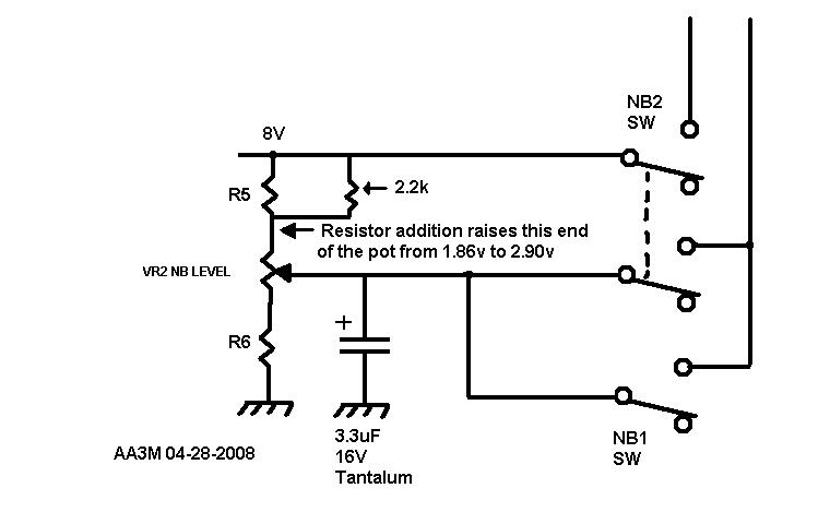
Here's a copy of the mod schematic.

The additional resistor raises the voltage available to Q605's emitter via the level pot (R2). See Figure 7 - Noise blanker circuit in maintenance manual.
The most active component of the mod is the addition of the capacitor to the wiper of the level pot (R2).
The capacitor value was chosen, just because. I believe it could just as well have been 0.1uf or 10uF.
It's purpose is to "stiffen" up the bias applied to Q605's emitter. When Q605 conducts, the emitter voltage changes
altering the base/emitter bias. (negative feedback)
I believe the mod would probably work by just adding the one cap. Once it began to work, I quit while I was ahead.
I didn't go back and pull the resistor out as you can see.
The voltage rating of the tantalum can be fairly low. The maximum voltage available out of the pot is about 2.90 volts.
A six volt unit would work just fine. I chose a tantalum type for their low leakage. You might get away with
an electrolytic, but electrolytics get tired over time. I must have pulled out bucket loads of failed electrolytics over the years.
The time between "working" and "failure" is the breeding ground of intermittants and unsolved problems.
Tantalums seem to like to fail in a "short" mode when they go. Rarely do I see tantalums go bad in properly designed circuits.
I noticed that I seem to have a "variety" of noises at my QTH. The blanker is more effective on some than others.
Have not been able to explain it, or define it. I can only say that I have observed it.
I apologize for the low quality photos. My old Sony Machiva camera died and it had a butt-kicking macro lens.
Will try to clean up the page as time permits.
73
John AA3M 4/28/08
This page has been read times.